
Flow Assurance and Infrastructure Safeguards in Upstream & Midstream Pipelines
In upstream production and midstream processing, operators must manage a highly volatile multi-phase fluid gas stream under unforgiving mechanical and environmental conditions, especially in Western Canada. Raw natural gas at the wellhead is heavily saturated with water vapour, light-end condensates, carbon dioxide (CO2), and hydrogen sulfide (H2S). As this rich, wet gas enters collection lines, any drop in ambient temperature or shift in pipeline pressure can trigger sudden, destructive phase changes.
Without rigorous upkeep and multi-staged chemical intervention, the consequences of unregulated phase changes are severe:
Pipeline Hydrates: When free water bonds with light hydrocarbons (like methane or ethane) under high pressure and cold temperatures, it forms solid, ice-like crystals known as methane hydrates. These hydrates accumulate rapidly, acting as structural plugs that choke flow lines, damage downstream valving, and can lead to pressure-induced pipeline ruptures.
Condensate Fallout & Corrosion: When gas temperatures drop inside the gathering lines, heavy hydrocarbons transition out of their gas phase and drop out as raw liquids (condensates). These fluids pool in low points throughout the pipeline network, restricting gas velocity and creating stagnant traps that accelerate internal line corrosion.
System Scaling: Mineral-heavy water carryover bakes directly onto high-temperature heat exchangers and firetubes, creating an insulating layer of mineral scale that accelerates equipment fatigue and corrosion while restricting heat transfer.
To maintain absolute flow assurance and insulate infrastructure from catastrophic failure, Western Canadian operations require a precise sequence of midstream processing glycols and heat transfer fluid programs: high-efficiency cavitation-inhibited coolants to drive field compression, highly stable bath glycols for intermediate thermal control, and elite liquid desiccants to dehydrate the rich gas and meet strict regulatory specifications.
The Regulations: Pipeline Tariff Specifications
To protect the shared infrastructure of pipeline networks, Canadian pipeline systems enforce uncompromising quality standards. These standards are commonly referred to as tariff specifications. Natural gas cannot simply flow continuously from the wellhead to the end-user without strict moisture, hydrocarbon, and pressure monitoring at every transfer point. This is done not only to satisfy the tariff specifications, but to protect the assets in the transmission network.
If a production facility or gathering node allows gas to slip past these defined thresholds, downstream operators will immediately execute a “shut-in” – cutting off the supply line and halting revenue until compliance is restored.
To satisfy these strict mandates and protect critical pipeline infrastructure, operators rely on specialized midstream processing glycols to protect high-load compression engines, drive liquid dehydration loops, and manage expansion cooling through inline pre-heaters before natural gas reaches municipal transfer stations and eventually the end user.
See the full Gas Quality Specifications on TC Energy’s Specifications Fact Sheet.
| Compliance Parameter | Canadian Tariff Constraint | Operational Threat of Non-Compliance |
|---|---|---|
| Maximum Water Content | 4 to 4.06 lbs / MMcf (65 mg/m³) | Triggers immediate structural hydrate formation; feeds acidic H₂S & CO₂ pipeline corrosion. |
| Hydrocarbon Dew Point | -10°C to -15°C @ Operating Pressure | Leads to heavy hydrocarbon liquid dropout, pooling, and fluid slugging in transmission lines. |
| Hydrogen Sulfide (H₂S) | Max 4 to 6 mg/m³ (~4 ppm) | Drastically accelerates sulfide stress cracking and catastrophic metal degradation. |
The Compression Phase – Transmission Efficiency & Auxiliary Systems
The first physical step in meeting tariff specifications requires elevating the pressure of the gas stream to support the transportation flow across Western Canada. As natural gas travels through thousands of kilometers of gathering networks and transmission mains, continuous friction against the interior pipe walls causes a steady drop in pressure and line velocity. To overcome these dynamic head losses and maintain required flow rates, the gas must be periodically re-pressurized at strategically spaced compressor stations. Boosting line pressures – often taking raw wellhead gas from 50 to 200 PSI and stepping it up to high-pressure transmission levels generally exceeding 1,000 PSI – is the mechanical requirement that keeps gas moving toward processing facilities and custody transfer hubs.
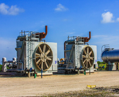
This critical compression phase relies heavily on massive stationary engines and field compressor units (such as Caterpillar & Waukesha models). Running 24/7 in remote Western Canadian environments, these high-displacement engines operate under relentless thermal loads and some of the most unforgiving and fluctuating field demands imaginable.
Keeping High-Load Compressors Running Efficiently
Large, high-horsepower natural gas engines and compressors run continuously under extreme loads. High-frequency piston vibrations in these engines cause the surrounding coolant to experience rapid pressure drops, generating microscopic vacuum bubbles. When these bubbles violently collapse it is called cavitation, and it will cause wet-sleeve cylinder liner pitting.
By utilizing an advanced coolant with specialized surface wetting agents, operators can change the surface tension of the fluid. This forces the vapour bubbles to form at smaller sizes, which creates a less violent collapse. These coolants also deposit a resilient microscopic film on the metal components to absorb implosion forces and protect engine internals against pitting.
Beyond the wellhead, these premium heavy-duty coolants are essential in compressors across the entire transmission network:
-
Compressor Stations: Keeping gas at a constant pressure for long-haul pipeline transmission and regional gathering.
-
Distribution Systems & Metering Stations: Supporting the machinery that re-pressurizes and accurately meters natural gas as it transitions to lower-pressure local distribution networks.
-
Processing Plants: Providing continuous, dependable thermal control for condensate stabilization systems, separators, and primary processing loops.
For High-Load Stationary Engines & Pipeline Compressors
Ultrakool SLH (Premium Heavy-Duty Coolant)
Our premier, fully formulated ethylene glycol-based coolant is engineered specifically for heavy-duty gas compression engines. Featuring a robust nitrite-based cavitation inhibitor and an advanced phosphate anti-scaling package, Ultrakool SLH contains zero amine or ammonium compounds—making it entirely non-injurious to copper, brass, or aluminum alloys. Its unique surface wetting-agent technology protects wet-sleeve cylinder liners from devastating cavitation pitting, while its high reserve alkalinity prevents fluid oxidation and thermal breakdown in remote, high-load oilfield environments.
The Dehydration Phase – Water Absorption & Thermal Regeneration
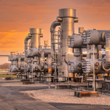
After passing through initial compression and inlet cooling loops to achieve its optimal operating window, the gas stream enters the Glycol Dehydration Unit (GDU). Here, specialized midstream processing glycols perform liquid desiccant dehydration—stripping entrained water vapor and depressing water dew points to ensure full compliance with strict pipeline tariff specifications.
The Mechanics of Glycol Dehydration
Inside the GDU Contactor Tower, wet process gas is pressurized and pushes its way upward while “lean” (highly concentrated) Triethylene Glycol (TEG) flows downward, physically absorbing the water vapour and content from the wet gas. This is made possible by forcing the gas upwards through the TEG using bubble cap trays. As the gas passes through the TEG, the glycol absorbs the moisture due to being highly hygroscopic. TEG not only absorbs the water in this wet gas, but it also preferentially absorbs some heavy hydrocarbons and VOCs such as Benzene, Toluene, Ethylbenzene, and Xylene.
As the TEG drops from tray to tray to the bottom of the contactor tower it retains as much water as possible forming “rich” TEG.
The Reboiler Loop: The water-laden “rich” TEG is sent then to a reboiler to boil off the absorbed water as steam, leaving high-purity, regenerated “lean” TEG to be recycled back to the top of the tower.

Maximizing Reboiler Operational Range Without Thermal Burning
Standard Triethylene Glycol possess a sctrict thermal limitation: if an operator pushes reboiler temperatures too high (Above 199°C to 204°C / 390°F to 400°F) in an attempt to achieve higher lean glycol purity (Less water, more pure TEG), the glycol molecules thermally degrade. This chemical breakdown creates corrosive organic acids and polymerizes into a thick, dark sludge that will destroy expensive circulation pumps, foul heat exchangers, and plug column packing.
Our specialized dehydration formulation solves this operational bottleneck. By integrating advanced, non-volatile thermal stabilizers, it safely expands the operator’s temperature limits by up to 10°F and can enhance water removal performance by up to 5%. This advanced chemistry allows users to safely increase reboiler temperatures a small amount to achieve a wider operational range and higher lean purity, without burning the glycol or driving asset degradation.
The Thermal Hand-Off: Waste Heat Recovery Integration
In high-efficiency gas plants, thermal management and dehydration intersect through multi-stage heat integration. Standard GDU design utilizes a Lean/Rich Glycol Heat Exchanger, where hot regenerated lean TEG exiting the reboiler transfers its heat to the cool, incoming rich TEG. This dual-action thermal swap cools the lean TEG down to optimal contactor tower inlet temperatures—preventing glycol vaporization and carryover losses—while simultaneously pre-heating the rich TEG before hitting the reboiler.
To further maximize plant efficiency, waste heat from hot Ultrakool SLH circulating through stationary compressor engines is captured via a shell-and-tube heat exchanger to provide supplemental pre-heating for cold process streams and rich TEG before they enter the GDU reboiler. Capturing this engine heat reduces the thermal load on reboiler burners, lowering site fuel gas consumption and operating emissions simultaneously.
For High Performance Dehydration & Enhanced Reboiler Stability
Ultra TEG (Inhibited Dehy Fluid)
Formulated with ultra-pure, virgin triethylene glycol, Ultra TEG is engineered specifically for natural gas dehydration systems. It features a built-in, non-volatile thermal stabilizer package that actively neutralizes organic acids and maintains a high reserve alkalinity. By preventing thermal breakdown and carbonaceous sludge formation under elevated operational windows, Ultra TEG allows for an optimized reboiler temperature range, keeps heat transfer surfaces clean, and drastically extends the operating life of expensive glycol-circulation pumps.

The Intermediate Heating Phase – Indirect-Fired Bath Heaters
The Thermodynamics of Pressure & Temperature
Just as in the stages of compression raising temperatures of natural gas, the reality in transport is that during expansion, the opposite will occur – both immediately and aggressively dropping the thermal state. As a general rule of thumb in gas thermodynamics, for every 100 PSI drop in pressure across a regulator valve, the gas temperature plunges by approximately 3.5°C to 4.5°C (6°F to 8°F). Without active thermal management, these rapid pressure drops quickly drag the gas stream well below freezing thresholds.
This thermodynamic challenge reaches its peak at municipal city gate stations, town border facilities, and district regulator hubs, where natural gas transitions from high-pressure midstream transmission pipelines into local utility distribution networks. To safely supply residential, commercial, and industrial city lines, high-pressure transmission gas (typically moving at 600 to 1,200 PSI) must be throttled down across massive pressure-reducing regulators to municipal distribution levels (often 60 to 200 PSI). A single-stage pressure cut of this magnitude can force an instantaneous gas temperature drop of 30°C or more! In cold Western Canadian environments, unheated gas entering a city gate station will instantly freeze trace water vapour into solid ice, causing regulator valves to lock up, creating severe equipment icing, burst pipelines, and risking catastrophic loss of municipal utility pressure.
The Role of Indirect-Fired Line Heaters
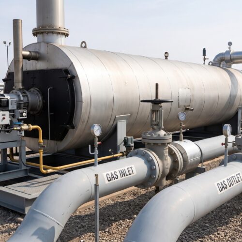
To offset this extreme thermodynamic cooling and preserve system integrity, midstream and utility operators deploy intermediate pre-heating systems positioned immediately upstream of the pressure-reduction skids. By routing the high-pressure gas through indirect-fired bath heaters or forced-circulation heat exchangers prior to throttling, operators raise the bulk gas temperature high enough to absorb the thermal effects of the immediate pressure differential. This pre-heating strategy ensures the gas remains comfortably above freeze points as it transitions through regulator valves, eliminating line-freezing, protecting municipal distribution equipment, and maintaining an uninterrupted flow of natural gas to local communities.
To safely elevate the process gas temperatures, just as mentioned above, the stream is routed through an indirect-fired line heater. Inside these units, the process gas lines run through a static, hot glycol and water bath that is heated by an internal firetube.
This application lacks the mechanical vibration and extreme localized pressure of a high speed combustion engine, and as such does not require a nitrite-based heavy-duty coolant. Instead indirect heaters require an industrial grade heat transfer fluid that is heavily optimized for pure thermal stability, scale mitigation, and long-term fluid oxidation control being that the glycol bath will be exposed to oxygen. If the bath fluid lacks high-temperature stabilizers, the intense heat of the firetube will literally bake the glycol—leading to rapid fluid breakdown, acidic pH drops, and a thick layer of baked-on scale that destroys heat transfer efficiency.
Optimized Heat Transfer for Indirect Line Heaters & Processing Baths
DynaTherm (Inhibited Ethylene Glycol)
Engineered specifically for closed-loop industrial heating networks and indirect bath heaters, Dynatherm is a high-performance, inhibited ethylene glycol fluid. By omitting expensive, engine-specific nitrite additives, Dynatherm delivers an exceptionally cost-effective solution tailored purely for thermal efficiency. It features an advanced industrial inhibitor package designed to passivate internal steel and copper piping while actively preventing fluid oxidation at high firetube temperatures. Its robust anti-scaling chemistry stops calcium and mineral drop-out, ensuring clean, scale-free heat transfer surfaces across a wide operational temperature range.

Midstream Facility Field Testing & Best Practices
In high volume midstream processing plants, remote gathering stations, and city gate facilities, gas lines are subjected to relentless thermal stress, and ongoing gas stream contamination. Over time, unmonitored degradation of midstream processing glycols silently compromises system efficiency – leading to acidic pH drops, inhibitor depletion, and localized scale buildup long before physical symptoms appear from the outside of the pipeline. By implementing routine, field-level testing protocols operators can be the primary line of defense against catastrophic component failures and unscheduled facility shutdowns or emergency turn-arounds throughout Western Canada’s harsh operating corridors.
Inhibitor Levels: Tracking active nitrite and chemical passivation levels in heavy-duty compression coolant loops is essential to guarantee cylinder wet-sleeve liners remain continuously protected against cavitation and pitting.
pH & Reserve Alkalinity Monitoring: Sour gas intrusion (H₂S & CO₂) and thermal breakdown generate corrosive organic acids in glycol loops. Regular field monitoring ensures your fluid maintains sufficient reserve alkalinity to neutralize these acidic contaminants before internal pipe, pump seal, and reboiler corrosion begins.
Glycol Concentration Verification: Operating at incorrect glycol-to-water ratios in thermal loops compromises thermodynamic performance. Routine concentration checks ensure precise freeze protection margins during brutal Western Canadian winters while preventing localized fluid boiling in high-temperature line heater baths.
Not Sure Which Process Glycol or Thermal Fluid Fits Your Operations?
Selecting the wrong glycol chemistry or neglecting stabilizer packages in sour environments can cause immediate pump seal failures, rapid heat exchanger fouling, and unscheduled plant shutdowns. Our technical team is here to assist with system engineering, fluid monitoring, and custom blending.
Whether you need to schedule a glycol system analysis or calculate the optimal TEG circulation rate for your contactor tower, we provide the bulk supply and technical support your midstream operation relies on.
Learn More About Glycol Solutions & Industries
System thermodynamics, metallurgy, and chemical demands vary drastically depending on the operational environment. Dive deeper into the technical mechanics, fluid dynamics, and preventative chemistry engineered for each specific application field: